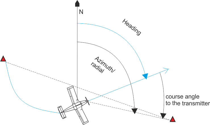
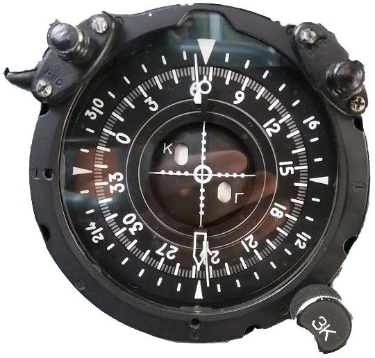
VOR (VHF Omni Directional Radio Range) is a radionavigation device that indicates the azimuth (radial) of the aircraft to/from the ground transmitter. For ease of understanding we will describe azimuth measurements using the orienteering compass principle.
Note: While using a classic magnetic compass we get a heading, an indication of the direction we are heading toward the north, the azimuth can be measured using the ”orienteering” compass. In the topography we select the landmark to which we want to measure the azimuth and subtract it from the magnetic north. This is also the case in radionavigation except that instead of the orienteering compass, we use the VOR receiver onboard plane and the VOR ground transmitter instead of the landmark.
As shown in the picture, the azimuth is the result of the sum of the course and the course from ADF (ADF gives the course between the aircraft and the radionavigation beacon – the beacon is the "magnetic” north).
The VOR device allows you to measure the deviation from the specified azimuth, as well as the meaning of the measurement (whether the aircraft is flying to or from the beacon - TO and FROM)
Division
VOR devices are divided according to principle into:
CVOR conventional VOR ("classic")
DVOR doppler VOR ("Doppler")
The difference is in ground equipment (signal generation and antennas), but the resulting signal is the same for the onboard receiver.
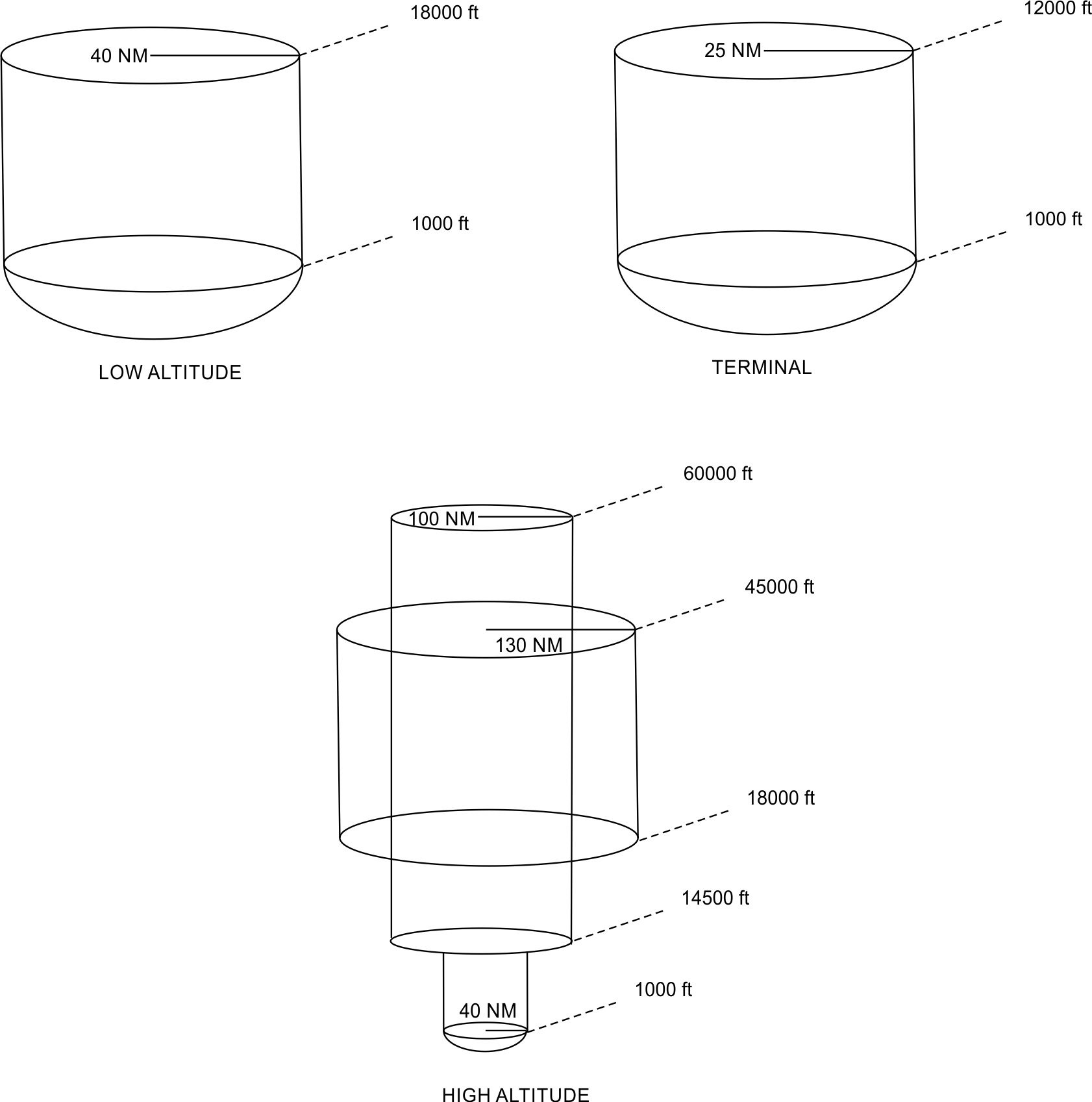
FAA further divides VOR according to usage:
High altitude
Low altitude
Terminal
Use
VOR is currently used as the main navigational device for radionavigation. The disadvantage of this use is that the VOR beacons are located at the points of interest of the flight paths/corridors which must be crossed first by plane before it can change the direction. This results in a limited number of aircraft in the corridor. Flight corridor flights should be discontinued with implementation the RNAV concept, for which the VORs do not achieve the necessary accuracy, so VOR beacons are not counted in the future.
Furthermore VOR is used in VOR/ILS, VORTAC, VOR/DME systems.
Frequency
The VOR beacon operates in the frequency range from 108 to 117.95 MHz. The range from 108 to 111.95 MHz is common to ILS and VOR, and therefore, only the frequencies that have first at number after dot (tenth of megahertz) even number and at second number after dot (hundredth of megahertz) is 0 or 5. More in ANNEX 10 / Chapter 5, 4.2.1
Function principle
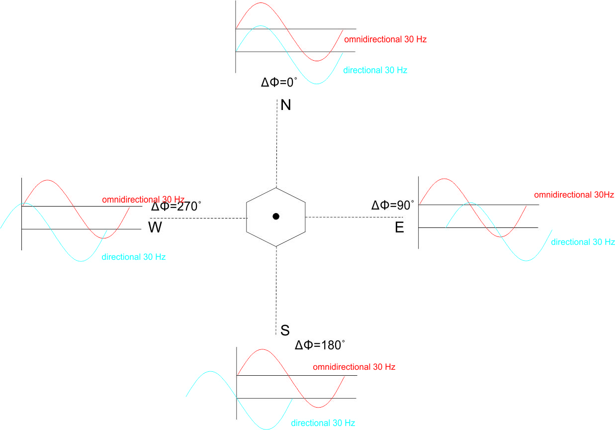
It is best to imagine the VOR as a classic lighthouse that shows to the ships a dangerous coastline. The lighthouse light rotates at a constant frequency and shines in all directions, but the sailor sees the light only when it is turned in his direction. Imagine that, in addition to the "classic" light from the lighthouse that is rotating, another omnidirectional light (for a brief moment) will light up every time when the rotating light intersects north. If we measure the time between seeing the light from the omnidirectional light and directional light crossing our position, we can calculate the azimuth. The VOR device works similar.
CVOR
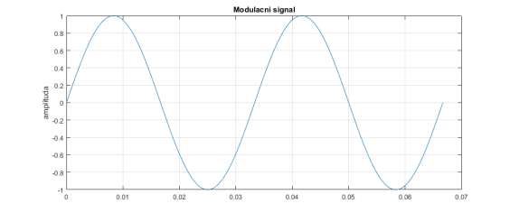
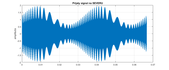
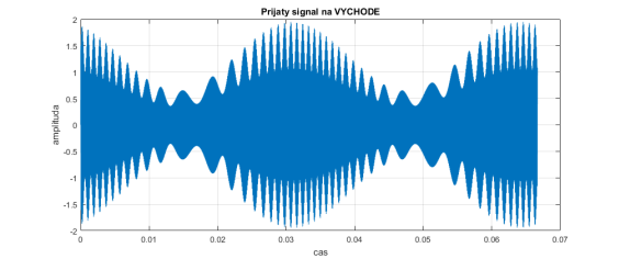
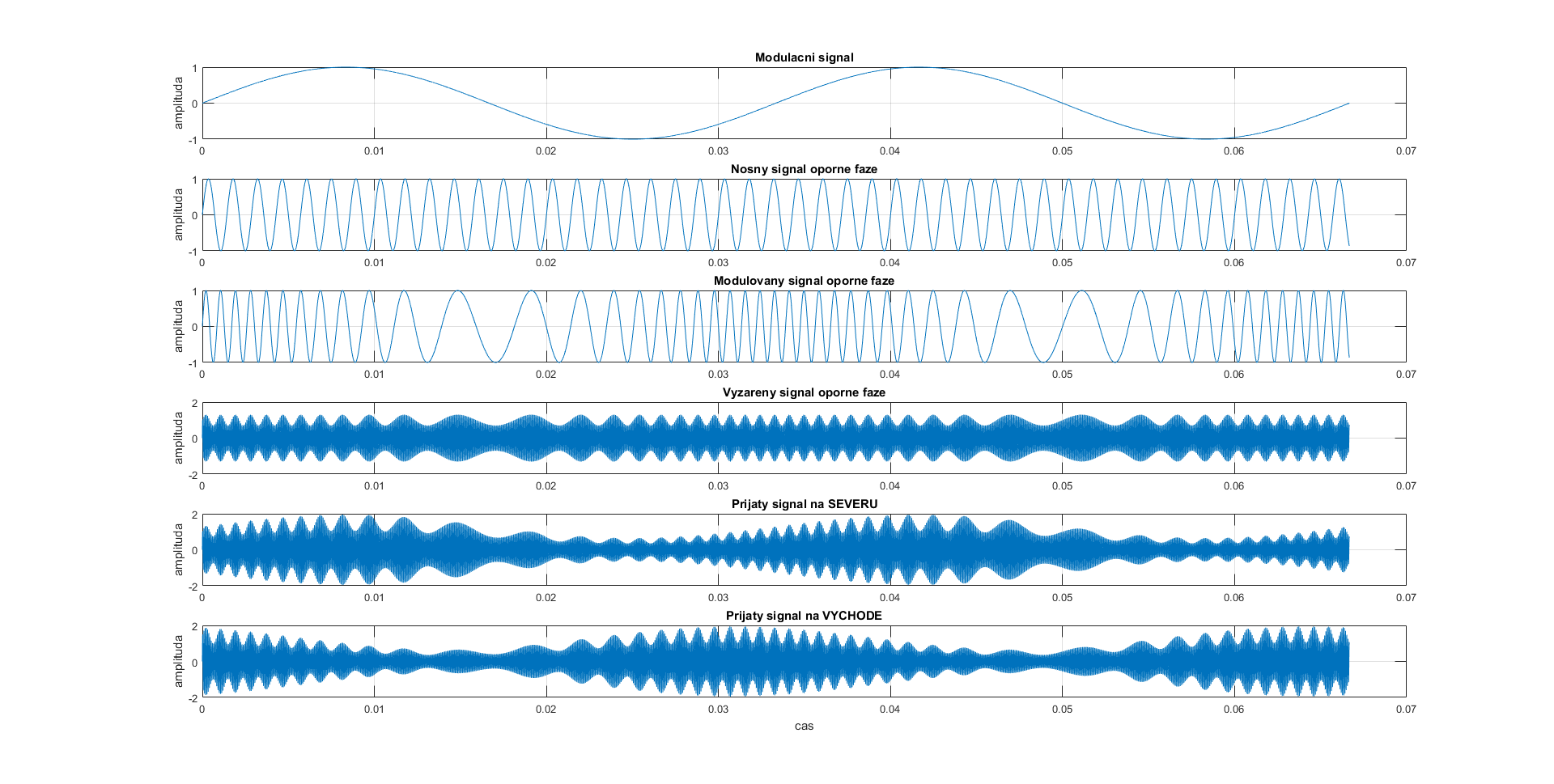
Instead of rotating light, VOR sends the directional radio signal. It is modulated on carrier frequency with amplitude modulation and frequency 30Hz. Furthermore, each time the VOR beacon crosses the north, it also sends an omnidirectional reference signal, also with a frequency of 30Hz. By comparing the omnidirectional and directional signal reception, the resulting azimuth (see animation) is then evaluated. However, in order for two 30 Hz signals not to interfere and not to deduct, they are modulated once with AM and once with FM modulation. Compared to the example of a lighthouse, when we considered the azimuth evaluation of the time difference between the directional and omnidirectional signals, the azimuth at VOR is calculated from the phase difference of the signals.
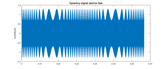
The carrier frequency is, as described above, modulated by directional signal with amplitude modulation of 30 Hz with variable phase (modulation depth 30%). It is then transmitted with a suppressed carrier. Practically, this signal is created by switching the antenna signal (Alford loop) at 1800 rpm.
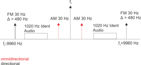
To avoid interference, the omnidirectional reference signal is first modulated by an AM signal with a ±9960 Hz modulation frequency (thus creating a "subcarrier").
This subcarrier - auxiliary carrier frequency is then modulated with the FM 30Hz signal with a 480Hz frequency shift.
By comparing these two modulated signals we get the resulting azimuth.
The 1020 Hz identification signal is also modulated on the omnidirectional signal, and it is also possible to modulate the voice communication on.
As the sideband (directional characteristic) is transmitted along with the omnidirectional characteristic, distortion of the symmetrical circular radiating characteristic occurs on the so-called "limacon pattern" (cardioid), which is the result of the sum of signals and so typical of the VOR.
Antenna unit
The CVOR signal is polarized horizontally and it is also necessary to adapt the antenna unit. The CVOR antenna is using the Alford loop antenna, which offers the most efficient use. The CVOR antenna is only one for both signals (directional and omnidirectional). VOR transmitter power circuits make signals that are transmitted to the antenna. Antenna consists of four elements into which individual signals are divided. One sideband (directional signal) is transmitted to the "northwest" and "southeast" antenna elements and the second band to the two remaining ones. Omnidirectional signal (with carrier) then to all 4 elements.
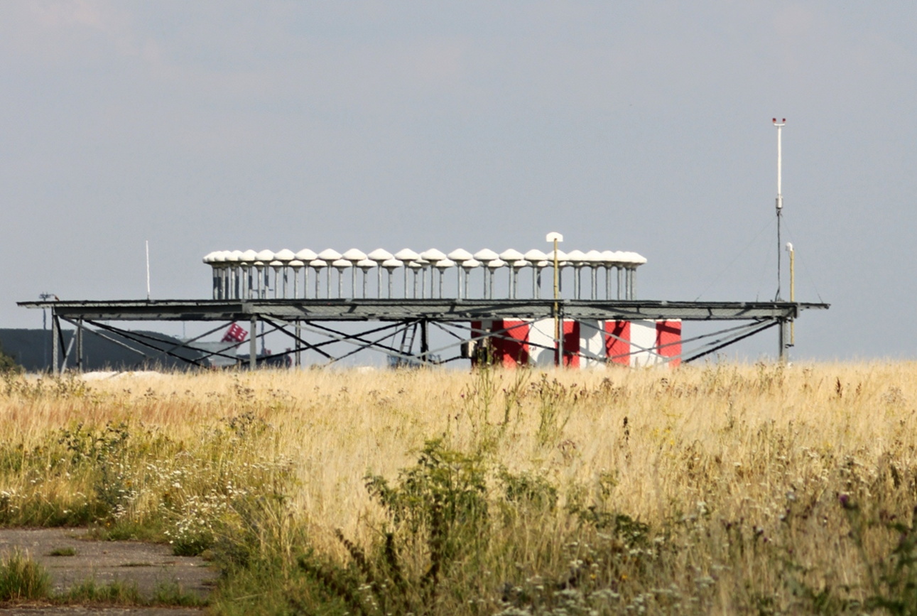
DVOR
At CVOR, the major disadvantage is a high number of inaccuracies when there are obstacles in the direction of radiation of electromagnetic waves. If the electromagnetic wave strikes an obstacle the phase of the transmitted signal changes, and the measurement onboard is then inaccurate. For this reason Doppler VOR - DVOR has been developed, to eliminate this negative attribute.
The DVOR is based on the Doppler principle, when the frequency of the incoming and outgoing waves appears different (the principle of passing the ambulance car etc.)
In opposite to the classical VOR, DVOR has transmitted signals modulated in reverse. This means that the omnidirectional-reference signal is transmitted by an omnidirectional antenna with a frequency of 30Hz with amplitude modulation. The directional signal is then transmitted by a rotating, electronically swept, circular bundle (the antennas are round about the omnidirectional antenna and the transmission is controlled electronically). If the antenna signal "rotates" at a frequency of 30 Hz, with an auxiliary carrier offset of ± 9960Hz, the Doppler effect causes the subcarrier to be modulated by FM modulation.
Antenna unit
At CVOR the directional signals (sideband) are transmitted by two opposing elements of the Alford loop (± 9960Hz), and at DVOR the signal is transmitted from two opposing antennas at the same time, ensuring transmission of the upper and lower sideband. As can be seen from the picture, the DVOR antenna consists of several elements beside at CVOR. The center antenna is used to transmit omnidirectional signals and circular antennas to sweep the directional (sidebands).
The directional signal sweep is controlled by "triggering" pulses from a pair of opposed antennas at the time the previous pair reaches the maximum amplitude of the pulse.
Compared to CVOR, the variable signal rotates counterclockwise.
To keep the frequency shift, the distance "R" between the omnidirectional and directional antennas must be maintained.
The difference between CVOR and DVOR is not recognized on board, so we do not have to have two different VOR receivers. The receiver compares the received signals, which are the same. The only difference is accuracy, because the use of DVOR can increase it.
The problem with DVOR is that the antennas that transmit the signal are very close together. This means that the transmitted signal from one antenna is up to 55% "absorbed" by the surrounding ones.
TTD
Frequency
108-117,95MHz
Frequency shift
50kHz
Power
Antenna
Omnidirectional
Radiation area
360°
Nav. unit
azimuth/radial
Accuracy
CVOR ±2°, DVOR ±0,2°
Range
300-400km
Polarization
horizontální
Frequency stability
Identification
2-3 morse sign at 1020 MHz
Note.: Azimuth is the angle in plane xz between the local meridian and the direction of the radionavigation device.