The NDB is a non-directional beacon which provides navigation data called bearing.
NDB works with a onboard device ADF (Automatic Direction Finder).
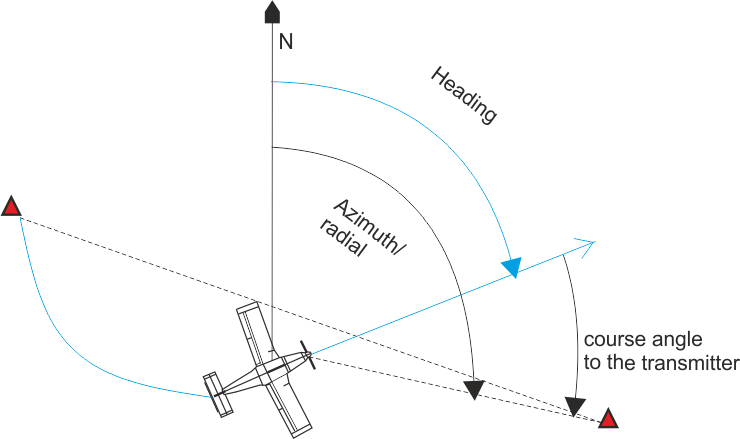
The principle of function between NDB and ADF can be described as a connection between the magnetic north and the classical compass. The needle of magnetic compass shows us due to the physical laws our orientation to the magnetic north - bearing. Similarly, when we "exchange" the magnetic north with the NDB beacon and the magnetic compass with the ADF, we get information about bearing we are flying (how is a nose of a plane oriented to the beacon). As with the principle of magnetic north, we only get a "course", not an azimuth (more about azimuth - VOR beacon).
Division
NDB can be divided by location where operates:
On the track - indicates interest points on flight corridors.
Approach - in the extended axis of the runway are beacons called NDB (Locator Outer) and L (Locator).
Application
As described above, the NDB is used to designate a particular navigation point, either on flight paths or when approaching on landing.
NDB can be used for marking flight corridors, space-based navigation or instrument approach landing.
Flights paths/corridors
When used for marking flight corridors, we can either use the "passive" method, when we direct ADF to NDB beacon and fly until we reach the beacon. The problem arises when we do not eliminate the dragging of the wind (we will reach NDB beacon, but in the worst case we can also arrive from the opposite side). The second option is an "active" flight, where we eliminate the drag of the wind comparing iformation from the ADF and the magnetic compass.
Space-based navigation
Determination of the position in the space (with an inaccuracy of ±5°!) is carried out by 2 NDB beacons, when we plot their bearing ±180° to the map and the intersections are within ±5° our position.
Instrument Approach
The last option is to use for landing, more precsisely only for instrument approach. Typically, NDB beacons are placed at 4 and 1 km along the extended runway axis.
NDB The NDB in the „Locator outer“ position must be identified by a group of 2 morse characters at a rate of 6/7 times per minute. When flying from the „secondary“ direction of landing, the order of these letters in the group turns. In addition, the optical and acoustic signaling of the NDB crossover must be provided.
L the NDB beacon in the "Locator" position must be identified by 1 morse character, at a rate of 12 times per minute. In addition, the optical and acoustic signaling of the L crossover must be provided.
In the future, NDB is not included in any concept due to high inaccuracies. Currently, civil/general aviation use NDB sporadically, especially for sports flying.
The advantage of NDB is the use of long/medium waves, thanks to which it is possible to provide signals even in hilly terrain and increase the range at low altitudes. It is then used, for its range, for navigation over the sea. A further advantage is the one-sided HORMON emergency radio connection.
Function principle
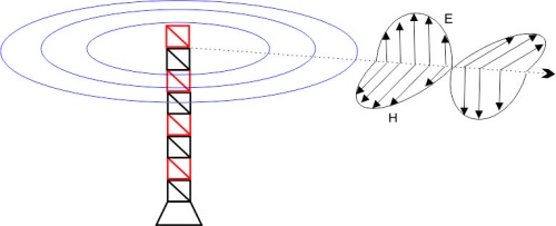
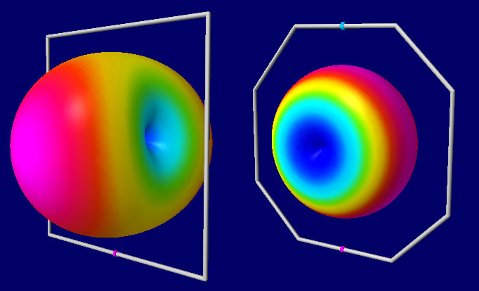
The principle of NDB beacon is very simple. Basically, it is only a transmitter that transmits a carrier signal over the antenna (modulated by the NON A1A, NON A2A). The signal pattern is transformed into a toroid ("tyre")characteristics by antenna. The transmitted signal is then received by the ADF on the airplane and evaluated in the form of "bearing".
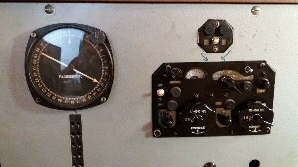
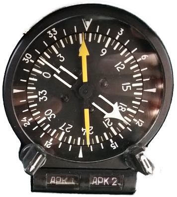
ADF
The ADF is a receiver on board of an aircraft, which, in cooperation with the NDB, evaluates and gives the radionavigation unit - bearing. ADF can work in two modes, in the "antenna" and "compass" modes. In the "antenna" mode, it is only the AM signal receiver (used to listen to the identification code of NDB or even the „classical“ FM radio), and in the "compass" mode it indicates the bearing.
Principle of ADF
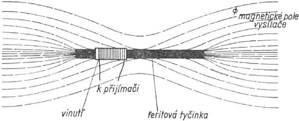
The magnetic field induces the voltage in the windings of the antenna, from which the ADF evaluates the direction of the incoming signal.
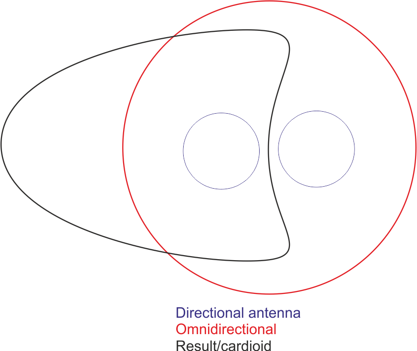
ADF has two antennas (directional and omnidirectional) to determine the direction of the incoming signal. The directional antenna uses either a ferrite or a frame antenna.
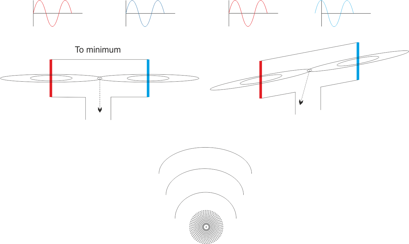
According to the function of these antennas, the incoming signal is focused by the directional antenna to a minimum. If the incoming signal "crosses" both "parts" of the directional antenna at the same time, then the phase difference is 0 and the directional antenna is directed to the minimum of the signal source (NDB). However, if the directional antenna is not precisely rotated, the NDB signal will arrive at each "part" of the antenna at different times and with another phase. The directional antenna attempts to always be turned so that the phase difference on the individual "parts" of the antenna is 0, so it is aimed at the minimum.
Since there may be ambiguity in the measurement (the minimum focus may be for two cases rotated by 180 °), the directional antenna is supplemented by the omnidirectional antenna. The resulting characteristic of the antennas is the so-called cardioid, which eliminates the ambiguity of the focus to a minimum.
(With the use of non-automatic radio direction finders - DF - the navigator had to know the position in relation to the beacon because it had no antenna to eliminate ambiguity).
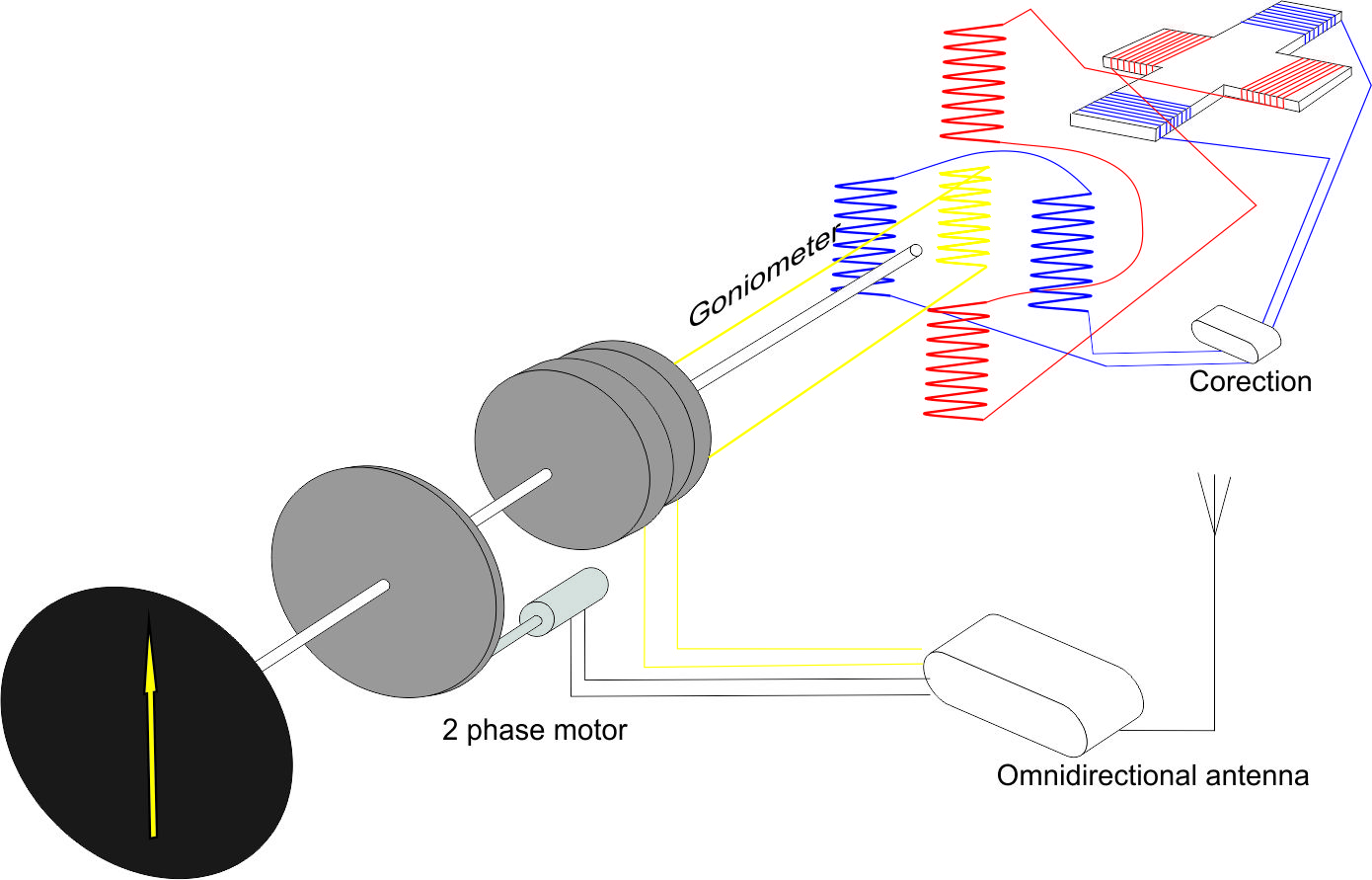
The use of the rotating antenna on modern aircraft is impractical, so a directional and omnidirectional antennas are used together in one "installation" located at the bottom of the aircraft. The bases are two perpendicular loop antennas that detect the incoming "direction" of electromagnetic waves. Furthermore, this system is made up of a goniometer whose central part is always trying to turn to minimums. Depending on which loops is signal detected, the voltage is induced on the respective coils, and the goniometer is going to focuse to the minimum. Of course there is also an omnidirectional antenna that performs the same function as the antenna described above.
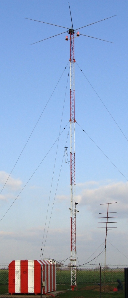
Antenna unit
For NDB, "umbrella" (low power) and "T-antenna" (high power) are used depending on the radiated power.
TD
Frequency
190-1750kHz
Frequency step
9/10kHz
Modulation frequency
400-1020Hz
Depth of modulation
95%
Frequency stability
1.10-4 (over 200W and or fr. 1606,5kHz 5.10-5)
Power
up to 5000W
Antenna
omnidirectional
Radiation area
360°,toroid
Nav. unit
bearing
Accuracy
±5°
Range
up to 500km
Polarization
vertical
Identification
2-3 morse code 7times/min.
Note: The radio wave consists of two components of the electromagnetic field (electrical components E and magnetic H). These components are perpendicular to one another - if H is vertically and E horizontally, it is a horizontal polarization (if E is vertically, then it is a vertical polarization).
Note: The frame antenna, which has an operating frequency ratio only about 5-30%, is excellent for receiving low frequencies but poor for broadcasting. Such a "small" antenna has a maximum on the sides of the antenna. On the contrary, if the so-called "full" antenna is used, these maxims are in the middle. ADF uses a "small" antenna (good reception, maximum at the sides).